PicoBlaze 8 bit Microcontroller
While VHDL provides all the resources necessary to build any electronic design from the ground up, sometimes its useful to install a more advanced component such as a microcontroller or microprocessor to handle tasks for us that would otherwise be complicated or time consuming if made from scratch.
The PicoBlaze is an 8 bit microprocessor built to be easily implemented in an FPGA and its design is compact and reliable. It has been widely used in the industry and academy.
The PicoBlaze is an 8 bit microprocessor built to be easily implemented in an FPGA and its design is compact and reliable. It has been widely used in the industry and academy.
|
| ||||
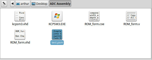
From KCPSM3.zip, take the files kcpsm3.vhd located in the VHDL folder and the files KCPSM3.EXE, ROM_form.coe, ROM_form.v and ROM_form.vhd located in the Assembly folder. The first one is the VHDL file that tells our VHDL compiler which ports connect where and forms the general electronic design of the microprocessor inside the FPGA.
The other files are three memory blocks (ROM) and the KCPSM3 compiler that turns the assembly instructions we create into a VHDL file that will be executed by our FPGA. That way we can write applications in assembly and the program will automatically transform them into VHDL for us to run in the FPGA.
As seen it can save a lot of time when creating designs but at the cost of the parallelism and control we typically get by using raw VHDL (or Verilog) code.
We write the assembly code and save it in .psm format. Here we show a sample psm from the tutorial.
| test.psm |
Next in order to compile our file we position ourselves inside the folder using our Terminal. Sadly the code was natively written for 32 bits Windows systems so we need to make use of a compiler to run DOS applications. In this example we make use of Dosbox which is an application that can run old programs (now you can guess how old this is...) from 32 bit platforms in both Windows and Linux 64 bits systems.
Install dosbox using apt or in Linux Mint from the link:
https://community.linuxmint.com/software/view/dosbox
After its done, type in the Terminal which should be inside the directory we're working on:
$ dosbox KCPSM3.EXE
It will automatically open the dosbox application and mount the drive on it. Otherwise we have to manually mount the drive C: on linux with mount c.
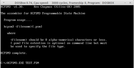
Once we have the application open, we repeat the compile command:
$ KCPSM3.EXE <FILE_NAME>.psm
in this case
$ KCPSM3.EXE TEST.PSM
Install dosbox using apt or in Linux Mint from the link:
https://community.linuxmint.com/software/view/dosbox
After its done, type in the Terminal which should be inside the directory we're working on:
$ dosbox KCPSM3.EXE
It will automatically open the dosbox application and mount the drive on it. Otherwise we have to manually mount the drive C: on linux with mount c.
Once we have the application open, we repeat the compile command:
$ KCPSM3.EXE <FILE_NAME>.psm
in this case
$ KCPSM3.EXE TEST.PSM
|
|
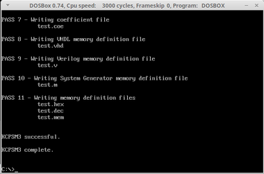
If everything went right it should indicate it has completed the operation. Now its time to load it on the FPGA. Initialize the ISE development enviroment, in Linux use:
$ ise &
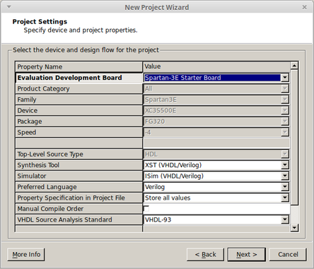
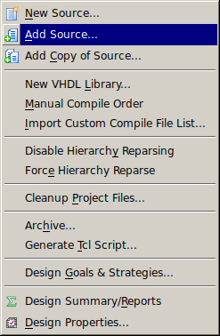
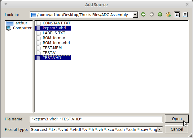
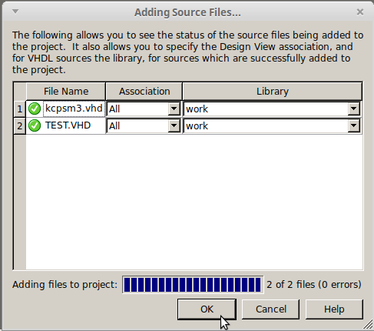
And create a new project. In this case we're using the definitions of the Spartan 3E which is the board we got to work with but you can use any of your boards. After creating the project, go to the menu Project->Add Source and select the files kcpsm3.vhd and test.vhd. The first one as explained before contains the directives VHDL needs to understand that it must work with a microprocessor, the second contains the assembly code of the application we built turned into a VHDL design.
$ ise &
And create a new project. In this case we're using the definitions of the Spartan 3E which is the board we got to work with but you can use any of your boards. After creating the project, go to the menu Project->Add Source and select the files kcpsm3.vhd and test.vhd. The first one as explained before contains the directives VHDL needs to understand that it must work with a microprocessor, the second contains the assembly code of the application we built turned into a VHDL design.
|
|
|
|
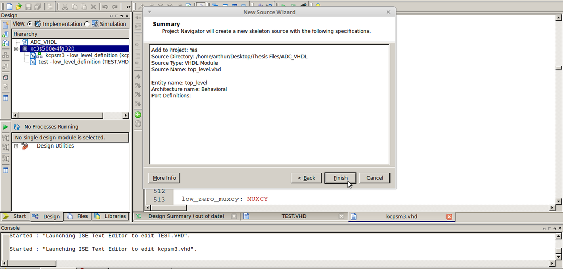
Next create a Source File of the VHDL Module type to link the instructions with the microprocessor.
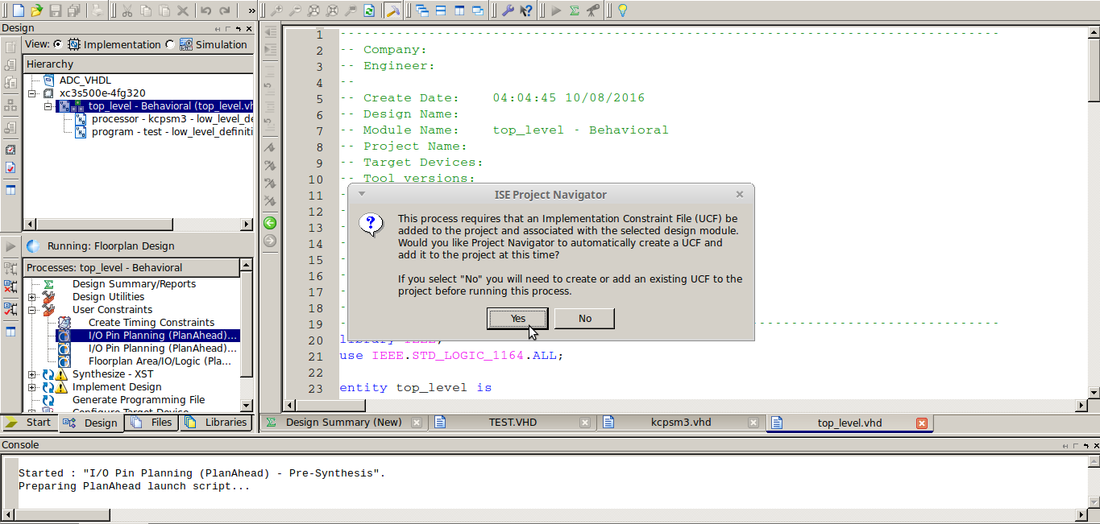
Next must link the VHDL files with the ports in the FPGA board, for that an UCF file must be made. In this case select I/O Pin Planning (Plan Ahead) Pre Synthesis
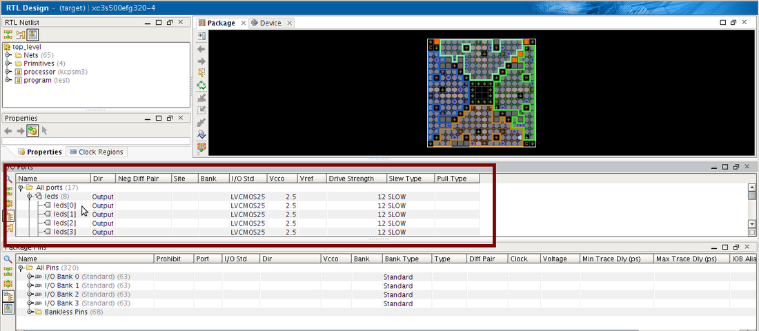
Which will open the Plan Ahead suite, we must edit the leds, inputs and clk to add the pins in our Spartan 3E board.
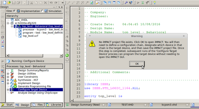
Next create and load the impact project.
And here are the barebone files used in the experiment.
|
|
|
| ||||||||
Counter with debouncer.
|
|
|
|
| ||||||||||
|
|
| ||||||
[1] http://eprints.qut.edu.au/55385/1/Spartan3E_Tutorial_2.pdf
