My First VHDL project - Part II
Next we're going to create a new entity and architecture. To do that double click on the Add new file option in the left menu.
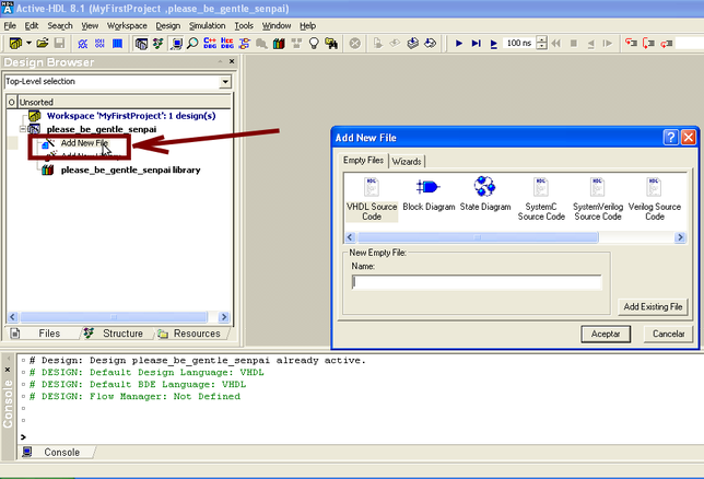
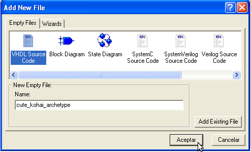
You must then assign a new name to your model and select the VHDL Source Code option. Once again it should be short and describe the component you're trying to make.
If you've reached this far then you should have a nice and cozy blank slate to work your new design into reality. For this option we'll start writing the VHDL code. VHDL consists of three sections:
*Library declaration. Just like in standard programming, you need to declare what libraries you'll be using on your designs.
*Entity. Where you declare the input and output ports of your entity.
*Architecture. Where you declare what your entity does.
*Library declaration. Just like in standard programming, you need to declare what libraries you'll be using on your designs.
*Entity. Where you declare the input and output ports of your entity.
*Architecture. Where you declare what your entity does.
Libraries.
Overall there're plenty of libraries to play with but it's recommended that you work only with the official IEEE ones due to the fact some boards may not be compatible with certain non-official libraries.
Usually you'll only need:
* ieee.std_logic_1164.all;
* ieee.numeric_std.all;
Declare the libraries using the prefix library as follows:
library ieee;
Followed by the modules you want to use:
use ieee.std_logic_1164.all;
use ieee.numeric_std.all;
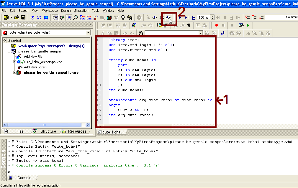
Afterwards we declare the entity and the architecture as shown on Figure 3. When finished we make click on the compile button to generate our bit code. If successful the compiler should indicate # Compile success and indicate if there was any Warning. If it fails to compile it will indicate the number of errors and (usually if you're lucky) the line where the error happened.
Usually you'll only need:
* ieee.std_logic_1164.all;
* ieee.numeric_std.all;
Declare the libraries using the prefix library as follows:
library ieee;
Followed by the modules you want to use:
use ieee.std_logic_1164.all;
use ieee.numeric_std.all;
Afterwards we declare the entity and the architecture as shown on Figure 3. When finished we make click on the compile button to generate our bit code. If successful the compiler should indicate # Compile success and indicate if there was any Warning. If it fails to compile it will indicate the number of errors and (usually if you're lucky) the line where the error happened.
The code for this project can also be downloaded from here.
| cute_kohai_archetype.vhd |
Testing our model
Now we need to test our model to see if it works. To do that we'll make use of Active-HDL's simulation tool. Still, in order to use it we must first configure it.
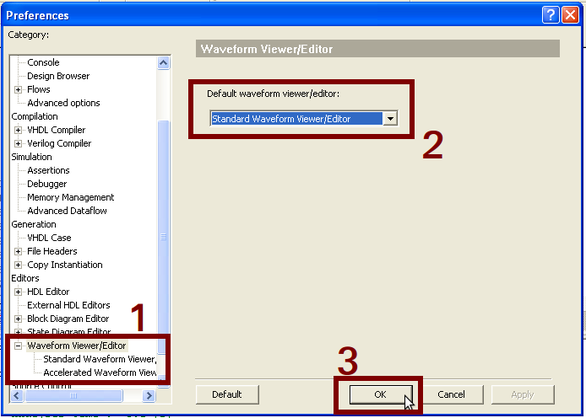
To do that go to the main Menu and select the option Preferences.
To do that go to the main Menu and select the option Preferences.
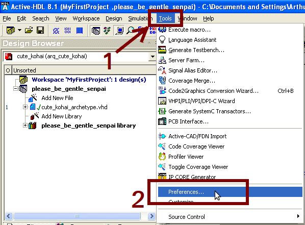
In Preferences we must select the Standard Waveform Viewer/Editor option rather than the default Accelerated Waveform Viewer/Editor to be able to play with the variables from our Design. Now it's ready for the testing phase!
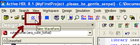
In order to start the simulation you must create a new Waveform. A waveform is a chart that displays the values of our variables and ports during the simulation to see what types of data are running through a given port in a given set of time. To do that select the New Waveform button in the main window as shown.
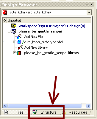
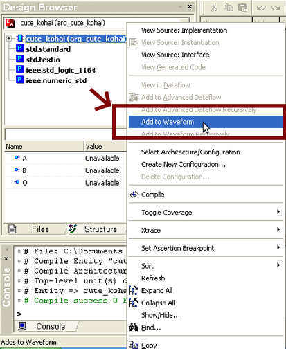
This will create a new sub window where you'll be able to monitor all the signals. In order to add the desired signal, click over Structure tag in the left panel as shown. Then select the design you want to simulate and right click over it, which will display a set of options to implement on the model. Select the Add to Waveform option.
|
|
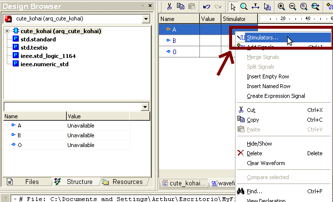
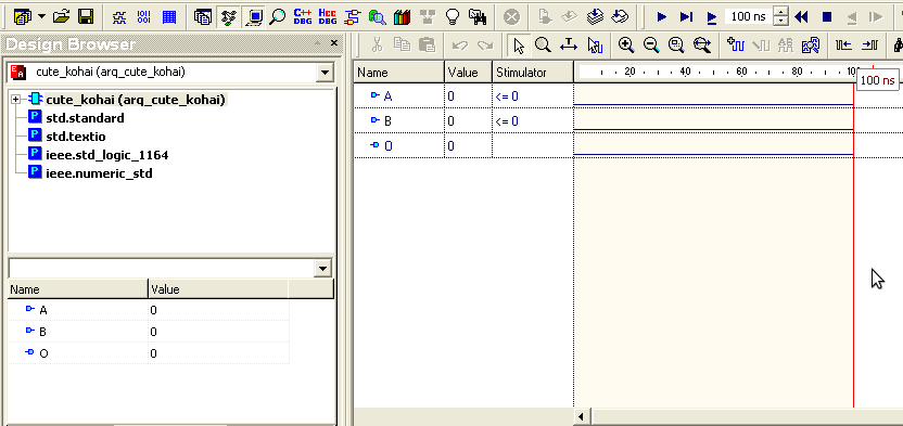
This will add each of the ports to the Waveform. Now it's time to introduce some signals to test the model. To do that right click over the A signal on the waveform as shown. Select the Stimulator option.
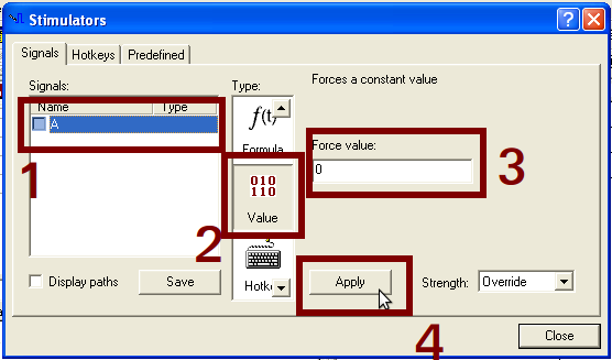
On the new window we must select the signal we want to stimulate. After that, the menu offers us many types of signals we can use to play with depending the data type we selected. On this case as its an std_logic data type we'll select the Value option.
This option lets us stimulate a given bit value or stream value depending the data type. Since we're working with an std_logic data type, we'll write a bit value, in this case a "0" to test our design.
Once written, we click on Apply and finally on Close. It's VERY IMPORTANT we click on apply before closing, otherwise the change won't take effect.
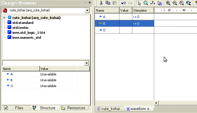
We repeat the process with the B signal, selecting whatever value we want to test. As the design we made is an AND gate, we'll be putting both into zero "0" to test it according to the truth table. From the truth table we know the resulting output should be one "0". The waveform window should show the following.
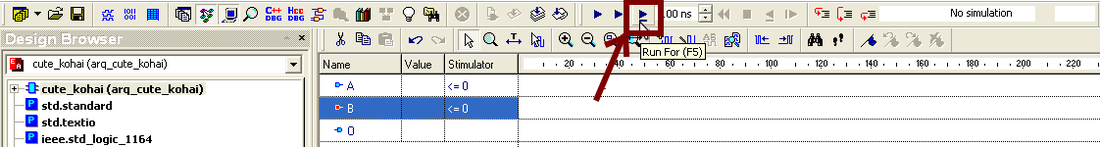
Now all that's left is to run the simulation. There're several ways to perform this, from having it run sequentially a specified number of seconds (very useful for counters) or having it run step by step. In this case given that we will be getting an output from a given set of inputs, we shall use the step by step simulation. Press the Run For (F5) button on the main simulation bar as shown in the Figure.
If everything worked well, you should be getting a new signal in the output port O of one "0".
We can zoom out to get a wider view of the waves using the zoom buttons on the waveform bar. Repeat the process changing the values of A and B to get all the different possible combinations for the AND gate and you'll see that you only get "1" when both A and B are one as it corresponds with its truth table.
And that's it! You now have your first working VHDL model! Rejoice!
And that's it! You now have your first working VHDL model! Rejoice!
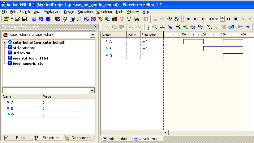
As per the AND truth table, O only is "1" when both A and B inputs are "1".
