Preliminaries.
Install Xilinx ISE.
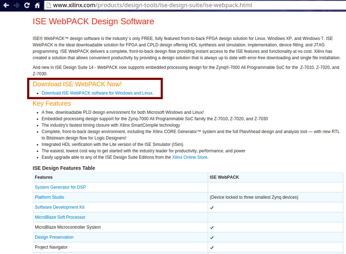
First the painful part. You must download ALL of the Xilinx ISE application to develop in FPGA. That thing weighs an average of 14? GB or something, online. So if you got a slow connection, it will be a pain.
To do that, go to the Xilinx page and seek the ISE. You can do so HERE.
To do that, go to the Xilinx page and seek the ISE. You can do so HERE.
Follow the installation procedure and place it in a folder you won't use much. I placed mine in a Programs folder as shown on Figure 2. The application can be selected from command line as shown.
One of my main complaints is the disordered nature of the software so I suggest you make a .bashrc in your computer to access the application without having to move all the way from home. Learning to write bash files really pays off in the long run.
One of my main complaints is the disordered nature of the software so I suggest you make a .bashrc in your computer to access the application without having to move all the way from home. Learning to write bash files really pays off in the long run.
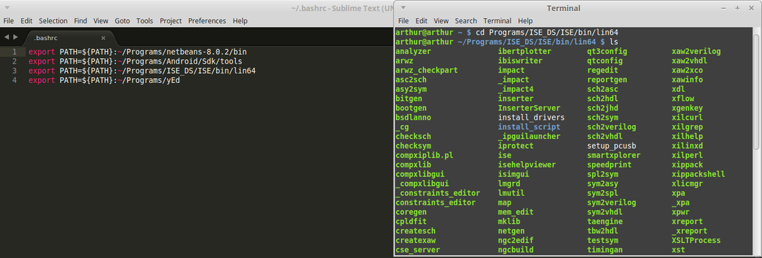
We test the application typing the command ./ise in the command line either in the directory where it's installed or anywhere if you included it on the .bashrc file.
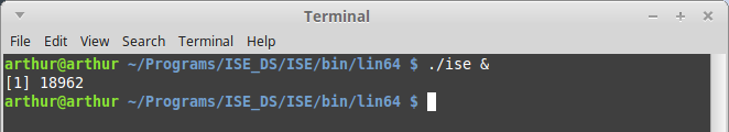
It will display the ISE logo as it loads...

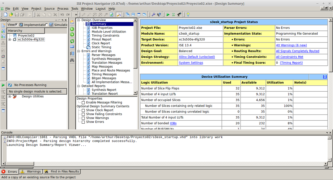
If it worked well, we'll find the cluttered mess that's the ISE editor.
Configuring the device.
Next thing you need in order to load the .bit code to the FPGA is to configure the ISE and the computer to recognize our device. Sadly Ubuntu doesn't recognize the FPGA straight from the box which makes it necessary to load the necessary USB drivers.
First of all we need to install the controllers for the usb cable. To do that we open a new terminal and type (or copy/paste) the following line:
$ sudo apt-get install fxload libusb-0.1-4 libusb-dev
First of all we need to install the controllers for the usb cable. To do that we open a new terminal and type (or copy/paste) the following line:
$ sudo apt-get install fxload libusb-0.1-4 libusb-dev

Then we create a new rules file that will input the FPGA information. In this case:
$ sed /home/YOUR_DIR_NAME/Xilinx12/ISE_DS/common/bin/lin64/xusbdfwu.rules -e 's:BUS=="usb", ::g' -e 's:SYSFS:ATTRS:g' -e 's:TEMPNODE:tempnode:g' > xusbdfwu_Nuevo.rules
Then we need to configure the rules files using either Gedit or your favorite text editor. It can be Vim, pico, nano or whatever you prefer.
$ gedit xusbdfwu_Nuevo.rules
Once we have it configured, we need to copy it to the computer's rules directory.
$ sudo cp xusbdfwu_Nuevo.rules /etc/udev/rules.d/xusbdfwu.rules
We can check if it was correctly copied by using the command:
$ ls /etc/udev/rules.d/xusbdfwu.rules
We must locate the .hex files with the command.
$ ls *.hex
And copy the files to the folder /usr/share.
$ sudo cp *.hex /usr/share/
Finally we must restart the udev file with the command.
$ /etc/init.d/udev restart
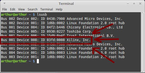
If the operation worked well, you can connect the FPGA to your computer, power it on and by typing the command:
$ lsusb
the vendor's tag should appear in the list of connected devices as shown on the figure.
$ sed /home/YOUR_DIR_NAME/Xilinx12/ISE_DS/common/bin/lin64/xusbdfwu.rules -e 's:BUS=="usb", ::g' -e 's:SYSFS:ATTRS:g' -e 's:TEMPNODE:tempnode:g' > xusbdfwu_Nuevo.rules
Then we need to configure the rules files using either Gedit or your favorite text editor. It can be Vim, pico, nano or whatever you prefer.
$ gedit xusbdfwu_Nuevo.rules
Once we have it configured, we need to copy it to the computer's rules directory.
$ sudo cp xusbdfwu_Nuevo.rules /etc/udev/rules.d/xusbdfwu.rules
We can check if it was correctly copied by using the command:
$ ls /etc/udev/rules.d/xusbdfwu.rules
We must locate the .hex files with the command.
$ ls *.hex
And copy the files to the folder /usr/share.
$ sudo cp *.hex /usr/share/
Finally we must restart the udev file with the command.
$ /etc/init.d/udev restart
If the operation worked well, you can connect the FPGA to your computer, power it on and by typing the command:
$ lsusb
the vendor's tag should appear in the list of connected devices as shown on the figure.