Programming VHDL.
On this short tutorial I intend to show what I've learned so far of VHDL so that you can make your own designs and impress the girls or something XD. This tutorial includes two sections, first the simulation phase where we'll be making use of Aldec Active-HDL v8.1 electronic simulator and the second is the load phase where we'll put the code inside a Spartan 3E Starter Kit from Xilinx. We've chosen this board because it's one of the cheapest and easiest to get your hands on.
If I have the time I'll try loading the code on a Nexys II to show you that it can be run on several boards without changing much.
If I have the time I'll try loading the code on a Nexys II to show you that it can be run on several boards without changing much.
The basics.
For this tutorial it's important that you understand:
*The basics of digital electronics (gates, registers, flip flops, and how to design digital circuits from truth tables).
*Some computer programming experience is desirable but not necessary as VHDL is very different from most sequential programming languages.
*How to operate a computer. Our examples will be run on the Linux Mint Rebecca OS while the simulator will be run on a Virtual Machine with Windows XP.
Entity and Architecture.
The most important element on VHDL are the entities and the architectures.
Basically an entity is the electronic design we're working on. For example, a single AND gate would be considered an entity, but so would something as complex as a microprocessor or microcontroller. Designs of every complexity can be described and modeled on VHDL, all it takes is the knowledge to implement them.
When declaring an entity we don't care about it's internal structure, all we care about is the inputs and outputs we need to make it work.
On VHDL an entity is declared as follows:
entity name_of_entity is
port(
input_bit1: in std_logic;
input_bit2: in std_logic;
.
.
.
input_array: in std_logic_vector(0 to size_of_array);
output_bit1: out std_logic;
output_bit2: out std_logic;
output_array: out std_logic_vector(size_of_array downto 0)
);
end name_of_entity;
In the previous example we declared n number of logical inputs using the std_logic data types. Inputs with that data type can only accept a single bit value which can be either one "1" or zero "0".
The input_array is a port of std_logic_vector type. This means that unlike the std_logic type it can accept up to size_of_array number of ones and zeros. So with a size of seven "7" std_logic_vector it would be able to accept from zero "0" to "7" ones or zeros bits. This is especially useful if we want to analyze bytes without having to declare a huge number of std_logic ports and is referenced the same way we reference an array in C/C++.
The output_bit1 and output_bit2 are outputs thanks to the out delimiter and are of std_logic type. That means that just like with input_bit1 and input_bit2, they're only able to send one zero "0" or a one "1" each. Meanwhile output_array is std_logic_vector type so it can send size_of_array bits.
While an entity defines the inputs and outputs of a given model, an architecture describes what's inside of it and what it does with the information it receives. An architecture defines what kind of operations a given entity can perform and it can be of three types.
*Structural. It's the one most similar to digital electronics and describes a given design in terms of gates and other electronic devices.
*Behavioral. It's the one most similar to regular programming and describes a design based on it's behavior and response to a given set of inputs.
*Register Transfer. It's used to instatiate designs that will be synthesized in other models.
No matter the type, an architecture is declared as follows:
architecture architecture_name is
signal signal_name1: std_logic;
signal signal_name2: std_logic_vector;
begin
WHATEVER WE WANT THE ENTITY TO DO. CAN BE STRUCTURAL, BEHAVIORAL OR AN HYBRID.
end architecture_name;
On this case we have declared an architecture that has two signals. Signals can be seen as variables and are usually used to transfer data between entities. A good analog in digital electronics would be that a signal is the equivalent of a wire connecting several different elements and circuits together. As such they don't have the in or out delimiters and only require to define if they're a std_logic or a std_logic_vector type.
My first VHDL design.
On this first practice we're going to simulate a simple gate circuit using Aldec Active-HDL v8.1 to illustrate the basics of VHDL design, then we're going to make something more interesting and load it on the Spartan 3-E board.
For now download Aldec Active-HDL software, you can do it from HERE.
Once you have it installed, initialize the application by double clicking it or selecting it from the Programs Menu.
For now download Aldec Active-HDL software, you can do it from HERE.
Once you have it installed, initialize the application by double clicking it or selecting it from the Programs Menu.
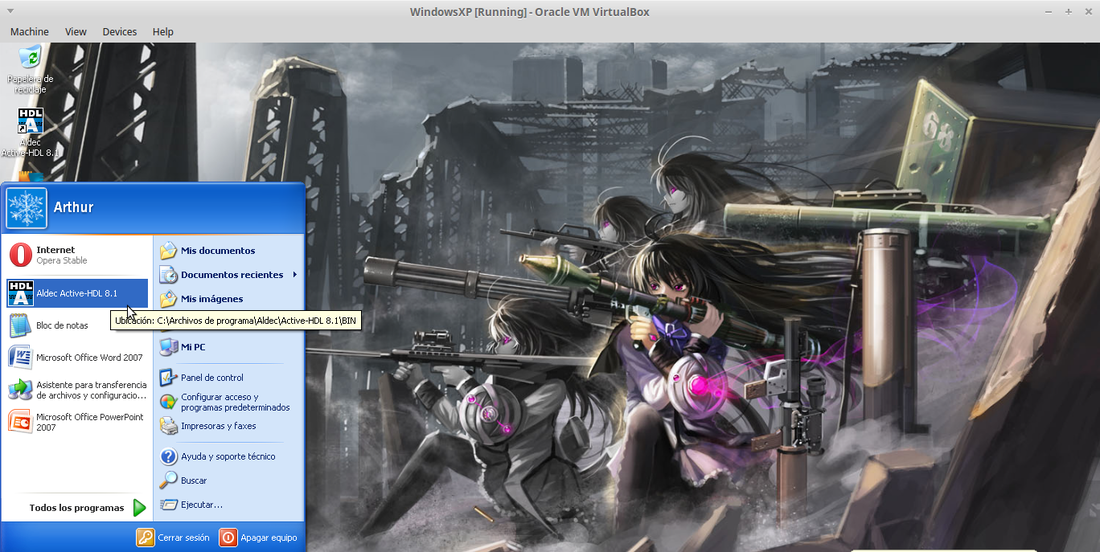
Figure 1. Initializing Aldec Active-HDL v8.1 along with my supercool desktop.
Once you have started the application it will display it's usual logo as seen on Figure 2.

If everything worked well, the application will display the main window as seen on Figure 3. If it's your first session, the application will request a Workspace. A workspace is a folder where the application will store all entities of a given project. You can have as many work-spaces as you want and ideally should make one for every big project you're working on to avoid over cluttering or confusion. For this application we'll create a new workspace called MyFirstProject.
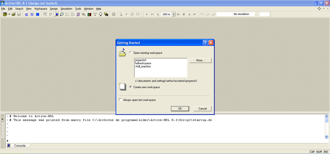
Once you select the Create new workspace option, it will ask for a new name. In this case we're going to call it MyFirstProject but you can call it whatever you want and for it's location we'll select the Desktop.
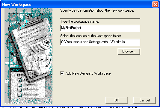
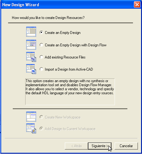
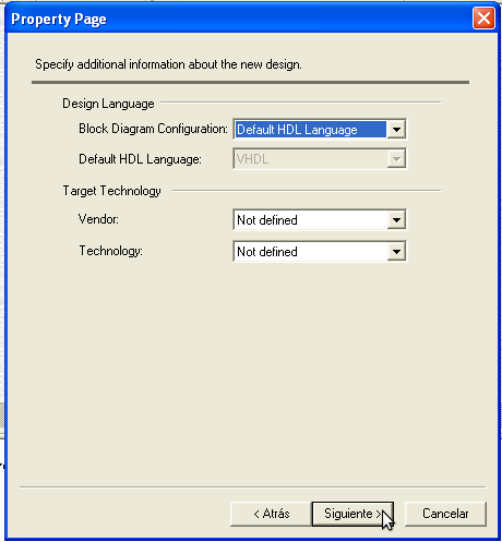
It will ask if you want to create a new Design. You can always cancel and do it later but since we want to create our first VHDL design, select the first option. The next window asks about the language type. Leave it as default.
|
|
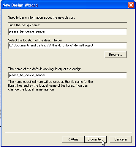
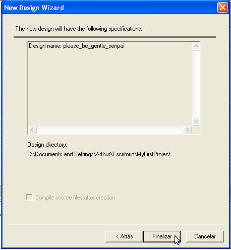
After that you need to specify the design name, which is what you're going to name your circuit. We can name it whatever we want so don't be afraid to get creative! Just keep it easy to remember and without spaces. The next window will ask if there's any other modification needed, we select Finish.
|
|
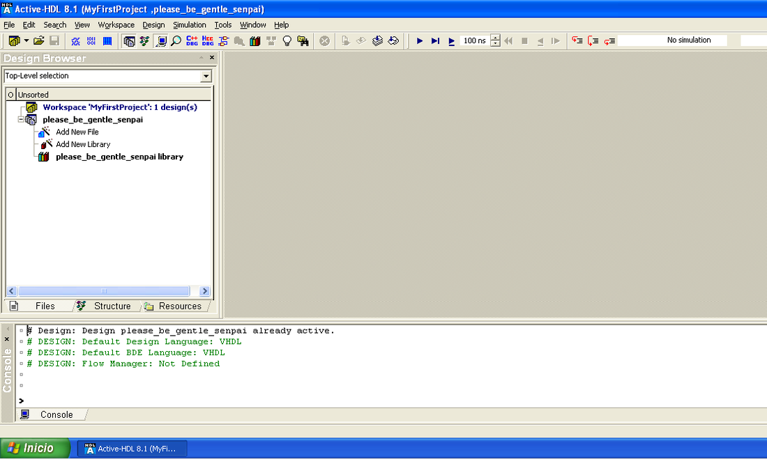
Once you finalize, it will go back to the main window and you'll be able to see your design on the left menu.